


Introduction
Xenon and mercury short arc plasma lamps exhibit the highest luminance and radiance output of any continuously operating light source and very closely approach the ideal model for a point source of light. In contrast to mercury and metal halide illumination sources, the xenon arc lamp is distinct in that it produces a largely continuous and uniform spectrum across the entire visible spectral region. Because the xenon lamp emission profile features a color temperature of approximately 6000 K (close to that of sunlight) and lacks prominent emission lines, this illumination source is more advantageous than mercury arc lamps for many applications in quantitative fluorescence microscopy. In fact, in the blue-green (440 to 540 nanometers) and red (685 to 700 nanometers) spectral regions, the 75 watt xenon arc lamp is brighter than a comparable 100 watt (HBO 100) mercury arc lamp. Similar to mercury lamps, xenon arc lamps are typically referenced using the registered trademark as XBO lamps (X for Xe or xenon; B is the symbol for luminance; O for unforced cooling), and were introduced to the scientific community in the late 1940s. The popular XBO 75 (a 75-watt xenon arc lamp) is more stable and has a longer life span than a similar HBO 100 mercury lamp, but the visible light emission constitutes only about 25 percent of the total light output, with most of the energy falling into the less useful infrared spectral region. Approximately 70 percent of the xenon arc lamp output occurs at wavelengths longer than 700 nanometers, while less than 5 percent of the output consists of wavelengths less than 400 nanometers. The exceedingly high pressure of xenon lamps during operation (ranging from 40 to 60 atmospheres) broadens spectral lines to yield far more uniformly distributed excitation of fluorophores when compared to the narrow and discrete emission lines produced by mercury lamps. Thus, the xenon arc lamp is more suited to stringent applications requiring the simultaneous excitation of multiple fluorophores over a wide wavelength range in analytical fluorescence microscopy.
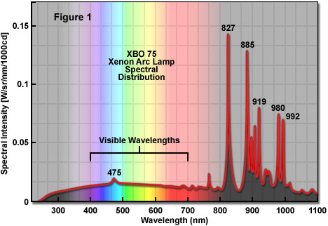
Even though xenon lamps produce broadband, almost continuous emission having a color temperature approximating sunlight in the visible wavelengths (often referred to as white light), they do exhibit a complex line spectrum in the 750 to 1000 nanometer region of the near-infrared spectrum (see Figure 1). In addition, several lower energy lines exist around 475 nanometers in the visible region. Between 400 and 700 nanometers, approximately 85 percent of the total energy emitted by a xenon lamp resides in the continuum whereas about 15 percent arises from the line spectrum. The spectral output (color temperature) of a xenon lamp is not altered as the device ages (even to the end point of the lifetime) and, unlike mercury arc lamps, the complete emission profile occurs instantaneously upon ignition. The xenon lamp output remains linear as a function of applied current and can be modulated for specialized applications. Furthermore, the spectral radiance is not altered by variations in lamp current. A typical XBO 75 lamp produces a luminous flux of approximately 15 lumens per watt, but the lamp requires several minutes after ignition to reach maximum light output due to the fact that xenon gas pressure inside the bulb continues to increase until it reaches the final operating temperature and achieves thermal equilibrium.
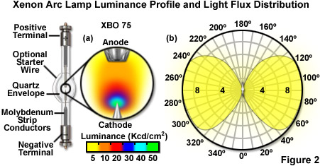
The maximum luminance distribution adjacent to the cathode in the arc region of an XBO 75 xenon lamp (often termed a hot spot or plasma ball) is approximately 0.3 x 0.5 millimeters in dimension and can be considered, for all practical purposes in optical microscopy, a point source of light that will produce high-intensity collimated beams when properly directed through a condensing lens system in the lamphouse. In most fluorescence microscopy applications, light gathered from the xenon lamp arc is imaged onto a pinhole or the objective rear aperture. A typical contour map of an XBO 75 lamp is illustrated in Figure 2(a) and the distribution of luminous flux intensity for the same lamp is mapped in Figure 2(b). In the contour map, the arc luminance is most intense at the tip of the cathode and drops off rapidly near the anode. The flux intensity pattern (Figure 2(b)) exhibits, for the most part, excellent rotational symmetry around the lamp, but is shadowed by the electrodes in the regions surrounding zero and 180° on the map where the intensity drops dramatically. In xenon arc lamps, the total lamp output ranges over 1000 nanometers in spectral bandwidth with the plasma arc and electrodes each accounting for approximately half of the total emission. The substantial contribution by the electrodes is due to their large surface areas and high temperatures. Most of the lower wavelength emission (in effect, the visible light) originates from the plasma arc, whereas the electrodes account for most of the infrared radiation (above 700 nanometers). The luminous and radiant intensity patterns generated by arc lamps are critical elements for engineers in the optical design and cooling strategy of light distribution systems for applications in optical microscopy.
Optical Power of Xenon (XBO) Arc Lamps
|
||||||||||||||||||||||||||||||||||||||||||
1ZEISS Filters 2Semrock Filters
Table 1
Presented in Table 1 are the optical output power values of a typical 75-watt XBO light source after passing through the microscope optical train and selected fluorescence filter sets. Power (in milliwatts/cm2) was measured at the focal plane of the microscope objective (40x fluorite dry, numerical aperture = 0.85) using a photodiode-based radiometer. Either a mirror with greater than 95% reflectivity from 350 to 800 nanometers or a standard fluorescence filter set was used to project light through the objective and into the radiometer sensor. The light throughput loss in a microscope illumination system can vary between approximately 50 and 99 percent of the input power, depending upon light source coupling mechanism and the number of filters, mirrors, prisms, and lenses in the optical train. As an example, for a typical research-grade inverted microscope coupled to an XBO lamphouse at the entrance port of the epi-illuminator, less than 70 percent of the light exiting the collector lens system is available for excitation of fluorophores positioned at the objective focal plane.
Orientation of a xenon lamp is critical to proper operation and longevity. In those lamps that are designed for vertical operation (up to an off-axis angle of 30°), the anode is positioned at the top, whereas the cathode lies underneath at the bottom of the lamp. This configuration is rotationally symmetrical and yields excellent arc performance. In contrast, lamps designed for horizontal operation (even though they can also be operated vertically) produce arcs that require stabilization in order to reduce premature and accelerated electrode wear. Horizontal lamp operation does not feature the symmetry inherent in vertical lamp operation, although this orientation is required by some lamphouse designs. Arc stabilization in horizontal lamps is most readily achieved using rod-shaped magnets mounted parallel to the lamp axis, directly under the envelope. The magnetic field pulls the arc downward, increasing the stability, which can be fine-tuned by varying the distance between the magnet and the envelope. Re-positioning of the lamp through a 180-degree rotation at lamp half-life enables the deposition of vaporized electrode material to become more evenly distributed on the inner walls of the envelope. It should be noted that the prudent choice is to employ vertical orientation of xenon lamps, whenever possible, in fluorescence microscopy configurations.
The useful life span of a xenon arc lamp is primarily determined by the decrease in luminous flux that occurs as a consequence of evaporated tungsten that is deposited on the inner wall of the envelope over time. Decay of the cathode tip and solarization effects of ultraviolet radiation on the quartz envelope also contribute to lamp ageing, as well as stability. Frequent lamp ignitions tend to accelerate electrode wear and lead to premature blackening of the envelope. The blackening gradually reduces light output and shifts the spectral characteristics to a lower color temperature. Lamp blackening, which increases the envelope operating temperature due to absorption of energy from radiated light, occurs slowly during the early stages of the lamp lifetime, but increases rapidly in later stages. Other factors that negatively impact xenon lamp life span include overheating, low current, power supply ripple, incorrect burning position, excessive current, and uneven envelope blackening. The average lamp lifetime (calculated by the manufacturers) is based on a burning period of approximately 30 minutes for each ignition event. The end of useful lamp life is generally agreed to be the point at which the ultraviolet light output has decreased by approximately 25 percent, the instability of the arc has increased beyond 10 percent, or the lamp has ceased to ignite altogether. In general, xenon lamps should be replaced (even if they are still able to ignite) when the average lifetime has been exceeded by 25 percent.
back to top ^Xenon Arc Lamp Construction
Xenon arc lamps are manufactured with spherical or ellipsoidal envelopes composed of fused silica quartz, one of the few optically transparent materials that is able to withstand the excessive thermal loads and high internal pressures imposed on materials used in the fabrication of these lamps. For most optical microscopy applications, the quartz alloy used in xenon lamps is typically doped with cerium compounds or titanium dioxide to absorb ultraviolet wavelengths that serve to generate ozone during operation. Typical fused silica transmits light at wavelengths down to 180 nanometers whereas doping the glass limits lamp emission to wavelengths above 220 nanometers. Xenon lamps equipped for ozone-free operation are often designated with the code OFR to indicate their class. Similar to the construction process in mercury lamps, the quartz used for xenon lamp envelopes is manufactured from the highest quality tubing, which is carefully formed on a lathe into the finished bulb via air expansion techniques. During operation, the lamp envelope can attain temperatures ranging between 500 and 700° C, necessitating tight fabrication tolerances to minimize the risk of explosion.
The anode and cathode electrodes in xenon arc lamps are fabricated from forged tungsten or specialized tungsten alloys doped with thorium oxide or barium compounds to reduce the work function and increase the efficiency of electron emission. Only the purest grades of tungsten are used in xenon arc lamp fabrication. High grade tungsten has a very low vapor pressure and ensures that xenon lamp electrodes are able to withstand the extremely high arc temperatures (over 2000° C for the anode) encountered during operation and helps to minimize the buildup of envelope deposits. Because of the complexity in machining electrodes with such high-purity grades of tungsten, ceramic tools are required throughout the process to avoid the introduction of contaminants. After fabrication, the cathode is brazed onto a molybdenum rod or plate for support, but the anode shaft consists of solid tungsten because it is subject to much higher temperatures due to constant bombardment of electrons emitted by the cathode. Both electrodes are ultrasonically cleaned and heat-treated to remove residual lubricants and contaminants before being sealed into the lamp bulb.
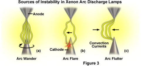
The design of xenon lamp cathodes has received a considerable amount of attention aimed at increasing stability of the arc during operation. In conventional lamps using thorium-doped tungsten electrodes, the arc emission point on the cathode intermittently shifts due to localized variations in electron emission from the surface, a phenomenon known as arc wander (see Figure 3(a)). This artifact, which increases in severity as the tip wears, leads to momentary fluctuations in lamp brightness referred to as flare when the arc relocates to a new region on the cathode (Figure 3(b)). Arc flutter describes the rapid lateral displacement of the arc column by convection currents produced as the xenon gas is heated by the arc and cooled by the inner walls of the envelope (Figure 3(c)). In addition, the sharp tips of thorium-doped cathodes tend to wear at an accelerated rate compared to cathodes fabricated with advanced rare-earth oxide alloys. Lamps featuring advanced cathode technology are often referred to as super-quiet and have demonstrated high short-term arc stability of less than one-half percent, as well as reduced drift rates of less than 0.05 percent per operating hour. Long term analysis of high performance cathode operation indicates that wear is significantly reduced, and shifting of the arc point over the average lamp lifetime is virtually eliminated. As a result, after a super-quiet xenon lamp is initially aligned with other elements in the microscope optical train, it is generally unnecessary to re-adjust the position over the entire operating life span of the lamp.
During the sealing stages of lamp assembly, the cathode and anode are fastened to strips of very thin molybdenum ribbon in a graded seal that compensates for thermal expansion differences between the quartz tubing and the metallic electrode shafts. A functional seal is produced by heat-compression of the quartz tubing to the molybdenum foil in a lathe placed under vacuum to prevent oxidation. The high compression temperatures enable the molten quartz to collapse around the molybdenum foil to form a gas-tight seal. After sealing the electrodes in the quartz lamp housing and annealing the assembly to remove strain, the envelope is loaded with high-purity (99.999 percent) xenon gas to a pressure of 10 atmospheres through a fill tube attached to the envelope bulb. The lamp is then cooled with liquid nitrogen to solidify the xenon gas and the fill tube removed to completely seal the envelope. After returning to room temperature, the finished lamp is pressurized as the xenon returns to the gaseous state.
The final stage of the xenon lamp assembly process consists of adding nickel-plated brass terminals termed ferrules or bases to each end of the bulb. The ferrules, which must be able to withstand temperatures up to 300° C, serve double duty by acting as electrical connections to the power supply as well as a mechanical support to precisely fix the lamp into the correct optical position within the lamphouse. Many ferrule designs include a flexible lead wire inside the base that connects to the sealed electrodes in order to eliminate the possibility of lamp failure due to stress or strain between the electrode shaft and the brass ferrule. Ferrules are attached to the sealed ends of the quartz envelope using carbon-graphite tape or a heat-resistant adhesive. A passivated compression ring is also used to ensure a tight junction between the ferrules and the envelope tube. After the ferrules are installed, an ignition wire is wrapped around quartz envelope at the edges of the elliptical bulb (see Figure 2). The wire is composed of thin, pure nickel and serves to create a localized electrical field within the envelope to assist in stimulation of electron ionization and flow at lamp startup.
back to top ^Xenon Lamphouses and Power Supplies
The design of lamphouses for xenon arc lamps is critical to the longevity and performance of the lamp. Foremost among design considerations is the fact that these lamps are operated at extremely high internal pressures (usually 50+ atmospheres) so the possibility of an explosion should be taken into account when selecting construction materials. Because arc lamps expand due to the excessive heat generated during operation, only one end of the lamp should be rigidly clamped to the housing; the other end can be secured with a flexible metal strip or covered with a heat sink and tethered to the appropriate internal electrical terminal through a cable (see Figure 4). Xenon lamphouses must be provided with sufficient cooling so that xenon lamps can be operated at less than 750° C at the envelope surface and less than 250° C at the base ferrules. Excessive temperatures rapidly lead to oxidation of electrode leads, produce accelerated envelope wear, and increase the potential for premature lamp failure. In the case of low power lamps (less than 250 watts), convection cooling in a well-ventilated lamphouse is usually sufficient, but lamps of higher power often require a cooling fan. The high trigger voltages (20 to 30 kilovolts) necessary to ignite xenon lamps require use of high-quality insulation materials in the lamphouse electrical wiring assembly and the power supply cable should be capable of withstanding voltages exceeding 30 kilovolts. In addition, the power cable should be as short as possible, unbundled, and placed away from the microscope frame and other metallic instruments (such as computers, filter controllers, and digital cameras) in the immediate vicinity.
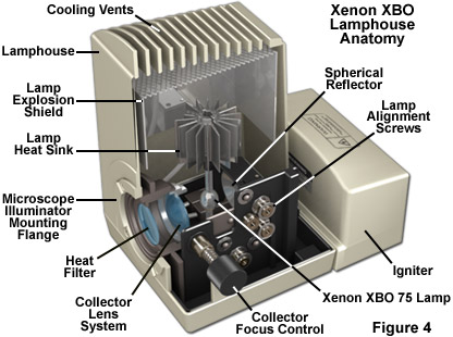
Most high-performance xenon lamphouses incorporate an internal reflecting mirror coupled to an output collector lens system that produces a collimated light beam of high intensity. Collection reflector designs range from simple concave mirrors to complex elliptical, spherical, aspherical, and parabolic geometries that more effectively organize and direct the lamp emission to the collector lens and subsequently through the microscope. The use of an electroformed conical reflector can achieve a nominal collection efficiency up to 85 percent, a vast improvement over conventional back-reflector systems, which have efficiencies ranging from 10 to 20 percent. Specialized reflectors can be readily designed by simple ray-tracing techniques. The coatings on all collection mirrors should be dichroic to enable infrared (heat) wavelengths to pass through. Xenon lamphouses also benefit from having infrared blocking filters, such as a Schott BG38 or BG39 glass filter and/or a hot or cold mirror (depending on the wavelengths transmitted or reflected), to attenuate or block infrared wavelengths and protect the specimen (living cells) from excess heat. Additionally, the solid-state detectors in electronic cameras, particularly those in CCD imagers, are also particularly sensitive to infrared light, which can fog the image if the appropriate filters are not inserted into the light path.
Xenon lamphouses generally follow a standard configuration with the arc lamp positioned at the focal point of the collector lens so that wavefronts leaving the source are gathered and roughly collimated to exit the lamphouse as a parallel bundle (Figure 4). The reflector is also placed on the same axis as the lamp and collector to ensure that an inverted virtual image of the arc can be created adjacent to the lamp. Light from the reflected virtual image is also gathered by the collector lens, thus increasing illumination power. A second lens system (termed the condensing lens), positioned within the microscope illuminator, is required to bring the parallel rays exiting the lamphouse into focus at the objective rear focal plane. In general, the focal length of the condensing lens system is much longer than the collector focal length, resulting in a magnified image of the arc being projected onto the objective rear focal plane. The final result is that light leaving the objective front lens and proceeding toward the specimen is roughly parallel to provide even illumination of the field of view. Note that during lamphouse alignment, light gathered by the collection reflector should not be directly focused on the envelope walls of the lamp (near the arc) to avoid direct heating of the bulb by its own emission light. This action will lead to the generation of excessive lamp temperatures. Instead, position the virtual image of the arc to one side or the other of the lamp.
One of the primary requirements of using a xenon arc lamp for quantitative fluorescence microscopy applications is that the emission output must be stable. The output radiant intensity of a xenon lamp is approximately proportional to the current flow through the lamp. Thus, to ensure maximum stability, the power supply must be carefully designed. Arc lamp power supplies must also incorporate a triggering device for lamp ignition. Illustrated in Figure 5 is the schematic diagram of a typical stabilized power supply for a xenon arc lamp. In addition to supplying the lamp with a stable direct current (DC) source, the power supply is also charged with maintaining the cathode at the optimal operating temperature using a specific current level. The stabilizing circuitry of a xenon arc lamp power supply, depending upon design, can stabilize the voltage, current, or the total power (voltage x current). If the voltage is stabilized, the current (and lamp brightness) will slowly decrease as the electrodes decay. In contrast, if the current is stabilized, the lamp will continue to emit at a constant level until the electrodes reach the critical point of deterioration that the lamp fails to ignite. On the downside, as increasing voltages are required to maintain a fixed current, the power sent to the arc slowly increases as the electrodes wear, which can result in overheating and the potential for an explosion. In power supplies that stabilize the total power level, the light output will slowly drop with current as the voltage needed to maintain the arc increases.
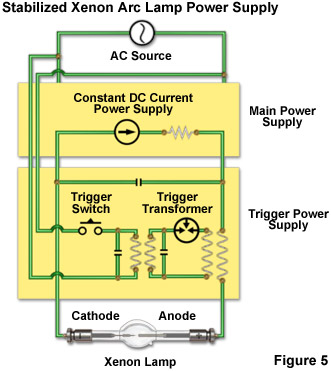
When arc lamps are cold (in effect, at room temperature), they act as electrical insulators and the xenon gas surrounding the electrodes must first be ionized to initialize and establish the arc. In most power supply designs, ignition is accomplished using high-voltage spikes (30 to 40 kilovolts) from an auxiliary circuit that produces a discharge between the electrodes. The specialized circuit is often referred to as a trigger or igniter because it applies a momentary high-frequency pulse to the lamp load through inductive coupling (see Figure 5). Once the arc is established, it must be maintained by a steady source of current from the main power supply, the value of which depends upon the lamp parameters. A typical 75 watt XBO lamp operates at a voltage of 15 volts and a current of 5 to 6 amperes, but these figures vary by manufacturer and increase with lamp power. Note that the XBO lamp operates at considerably higher current than would be expected from the relatively low voltage, which is specified by the size of the arc gap, xenon pressure, and the recommended operating temperature. Current ripple from the power supply must be minimized to ensure long arc lamp lifetimes. Thus, the quality of the direct current used to drive the lamp must be high and ripple should be less than 10 percent (peak-to-peak) for xenon lamps up to 3000 watts in power.
Specialized xenon lamphouses produced by aftermarket manufacturers often incorporate wavelength selection options and couple the output to an optical fiber or liquid light guide for relay to the microscope optical system for highly efficient illumination in selected regions of the spectrum. Examples include the Lambda LS (Sutter Instrument), which incorporates a xenon lamp, cold parabolic mirror, and power supply into a single enclosure that is coupled to a liquid light guide. The Lambda LS can accommodate an internal filter wheel, filter inserts, and a second externally mounted filter wheel. A more advanced and faster unit from Sutter, the DG-4, is able to produce wavelength switching speeds in the 1-2 millisecond range utilizing a dual-galvanometer design coupled to standard interference filters. Light from the xenon arc lamp is focused on the first galvanometer, which directs it to an interference filter by reflection from a parabolic mirror. The filtered light then passes through a second parabolic mirror and galvanometer before entering a liquid light guide. A cold mirror placed before the light guide eliminates infrared radiation from reaching the microscope optical train. Other manufacturers also produce similar xenon-powered illuminators, many of which feature wavelength selection and light shutters.
Contributing Author
Michael W. Davidson - National High Magnetic Field Laboratory, 1800 East Paul Dirac Dr., The Florida State University, Tallahassee, Florida, 32310.