


Introduction
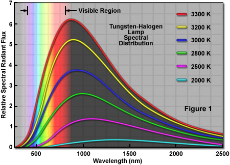
Incandescent light sources, including older versions with tungsten and carbon filaments, as well as the newer, more advanced tungsten-halogen lamps, have been successfully employed as a highly reliable light source in optical microscopy for many decades and continue to be the one of the illumination mechanisms of choice for a variety of imaging modalities. Older lamps equipped with tungsten wire filaments and filled with inert argon gas are frequently used in student microscopes for brightfield and phase contrast imaging, and these sources may be sufficiently bright enough for some applications requiring polarized light. Tungsten lamps are relatively inexpensive (compared to many other light sources), easy to replace, and provide adequate illumination when coupled to a ground glass diffusion filter. These features are primarily responsible for the widespread popularity of incandescent light sources in all forms of optical microscopy. Tungsten-halogen lamps, the most advanced design in this class, generate a continuous distribution of light across the visible spectrum, although most of the energy emitted by these lamps is dissipated as heat in the infrared wavelengths (see Figure 1). Due to their relatively weak emission in the ultraviolet portion of the spectrum, tungsten-halogen lamps are not as useful as arc lamps and lasers for examining specimens that must be illuminated with wavelengths below 400 nanometers.
Several varieties of tungsten-halogen lamps are now the default incandescent illumination source (and are provided by the manufacturer) for most of the teaching and research-level microscopes marketed around the world. They are excellent for brightfield examination, photomicrography, and digital imaging of stained cells and tissue sections, as well as numerous reflected light applications for industrial manufacturing and development. Polarized light microscopes used for particle identification, fiber analysis, and birefringence measurements, as well as routine petrographic geological applications, typically use high power tungsten-halogen lamps to provide the necessary light intensity through crossed polarizers. Stereomicroscopes also take advantage of this ubiquitous light source in both entry-level and advanced models. For imaging living cells with contrast-enhancing techniques (principally differential interference contrast (DIC) and phase contrast) in transmitted light compound microscopes, the most common light source currently in use is the 12-volt, 100-watt tungsten-halogen lamp. In long-term experiments (typically, those requiring hundreds to thousands of image captures), this lamp is particularly stable and is subject to only minor levels of temporal and spatial output fluctuation under normal operating conditions.
The first commercial incandescent lamps equipped with tungsten filaments were introduced in the early 1900s. These advanced filaments, which could be looped, coiled, and operated at very high temperatures, were found to be far more versatile than their carbon and osmium-based predecessors. Carbon lamps suffer from rapid vaporization of the filament at temperatures above 2500° C and thus, must be operated at lower voltages to produce light having a relatively low color temperature (yellowish). In contrast, tungsten has a melting point of approximately 3380° C and can be heated to almost this temperature within a glass envelope to generate light having a higher color temperature and life span than any of the previous materials used for lamp filaments. The major concern with tungsten lamps is that, during normal operation, the filament continuously vaporizes to produce gaseous tungsten that slowly reduces the filament diameter and eventually solidifies on the inside of the glass envelope as a blackened, sooty deposit. Over time, the lamp output diminishes as the residue of deposited tungsten on the inner envelope walls grows thicker and absorbs increasing amounts of the shorter visible wavelengths. Likewise, the loss of tungsten from the filament reduces the diameter, leaving it so thin that it ultimately fails.
Tungsten-halogen lamps were first developed in the early 1960s by replacing the traditional glass bulb with a higher performance quartz envelope that was no longer spherical, but tubular in shape. In addition, minute amounts of iodine vapor were sealed inside the envelope. Replacement of the lower-melting glass by quartz was necessary because the halogen regenerative cycle of the lamp (discussed in detail below) requires the envelope to be maintained at a high temperature (in excess of those tolerated by ordinary glass) to prevent tungsten halogen compounds from solidifying on the inside surface. Because of the new components, these advanced lamps were originally referred to using the term: quartz-iodide. Although lamps containing halogens represented a significant improvement over the plain tungsten bulbs they replaced, the new lamps featured a slight pinkish tinge that is characteristic of iodine vapor. In addition, quartz is readily attacked by the mild alkalis formed during operation, leading to premature failure of the envelope itself. In following years, bromine compounds replaced iodine and the envelope was fabricated with newer borosilicate glass alloys to produce tungsten-halogen lamps having even longer life spans and higher radiant output.
As previously discussed, in traditional incandescent lamps, vaporized gaseous tungsten from the filament is transported through the vapor phase and continuously deposited on the inside walls of the glass bulb. This artifact serves to blacken the inner walls of the bulb and gradually reduces light output. In order to maintain light loss at the lowest possible levels, conventional tungsten lamp filaments are housed in large bulbs having sufficient surface area to minimize the thickness of deposited tungsten that builds up over the life span of the lamp. In contrast, the tubular envelope in tungsten-halogen lamps is filled with an inert gas (either nitrogen, argon, krypton, or xenon) that is mixed during assembly with a minute amount of a halogen compound (usually hydrogen bromide; HBr) and trace levels of molecular oxygen. The halogen compound serves to initiate a reversible chemical reaction with tungsten evaporated from the filament to yield gaseous tungsten oxyhalide molecules in the vapor phase. Thermal gradients formed as a result of the temperature differential between the hot filament and the cooler envelope contribute to interception and recycling of tungsten to the lamp filament through a phenomenon known as the halogen regenerative cycle (illustrated in Figure 2). Thus, vaporized tungsten reacts with hydrogen bromide to form gaseous halides that are subsequently re-deposited onto cooler areas of the filament rather than being slowly accumulated on the inner walls of the envelope.
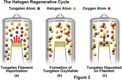
The halogen regenerative cycle can be dissected into three critical steps that are outlined in Figure 2. At the start of operation, the lamp's envelope, fill gas, vaporous halogen, and filament are initially in equilibrium at room temperature. When power is applied to the lamp, the filament temperature rises rapidly to its operating temperature (in the vicinity of 2500 to 3000° C), a sequence of events that also heats the fill gas and the envelope. Eventually, the envelope achieves its stable operating temperature, which ranges from 400 to 1000° C, depending upon the lamp parameters. The temperature differential between the filament and the envelope creates thermal gradients and convection currents in the fill gas. Once the envelope reaches a temperature of approximately 200 to 250° C (depending on the nature and amount of halogen vapor), the halogen regenerative cycle begins. Tungsten atoms evaporated from the filament (see Figure 2(a)) react with gaseous halogen vapor and the trace levels of molecular oxygen to form tungsten oxyhalides (Figure 2(b)). Instead of condensing on the hot inner walls of the envelope, the oxyhalide compounds are circulated by convection currents back to the region surrounding the filament where they decompose, leaving elemental tungsten re-deposited on the cooler regions of the filament (Figure 2(c)). Once free of combined tungsten, the oxygen and halide compounds diffuse back into the vapor to repeat the regenerative cycle. Continuous recycling of metallic tungsten back and forth between the vapor phase and the filament maintains a more uniform wire thickness than would otherwise be possible.
The benefits of the halogen regenerative cycle include the ability to use smaller envelopes that are maintained in a clean, deposit-free condition during the life span of the lamp. Because the envelope is smaller than those used in conventional tungsten lamps, expensive quartz and related glass alloys can be more economically employed during fabrication. The stronger quartz envelopes enable higher internal gas pressure to be used to assist in suppression of filament vaporization, thus allowing increased filament temperatures that produce more luminous output and shift emission profiles to feature a greater proportion of the more desirable visible wavelengths. As a result, tungsten-halogen lamps retain their original brightness throughout their life span and also convert electric current to light more efficiently than their predecessors. On the downside, the tungsten vaporized and re-deposited by the halogen regenerative cycle is not returned to its original location, but rather winds up on the coolest regions of the filament, resulting in uneven thickness. Eventually the lamps fail due to decreased filament thickness in the hottest regions. Otherwise, tungsten-halogen lamps might feature almost infinite life spans.
Early investigations revealed that the addition of fluoride salts to the vapor sealed inside tungsten-halogen lamps produced output with the highest level of visible wavelengths, and also deposited recycled tungsten on regions of the filament with higher temperatures. This discovery instilled hope that tungsten filaments could be maintained at a more uniform thickness throughout a dramatically increased life span for these lamps. Furthermore, the shifting of lamp emission profile output to include more visible wavelengths was highly desirable compared to the lower color temperatures afforded by similar lamps having alternative halogen compounds (iodide, chloride, and bromide). Unfortunately, fluoride compounds were discovered to aggressively attack glass (note that hydrofluoric acid is commonly used to etch glass) leading to premature failure of the envelope. Thus, fluoride compounds are not useful for commercial lamps. As a consequence, the bromide compounds discussed above are still the reagent of choice for production of tungsten-halogen lamps, but the lamp manufacturers continue to research the application of new fill gas and halogen mixtures for these highly useful light sources.
Tungsten-halogen incandescent lamps operate as thermal radiators, meaning that light is generated by heating a solid body (the filament) to a very high temperature. Thus, the higher the operating temperature, the brighter the light will be. All tungsten-based lamps exhibit emission spectral profiles resembling that of a blackbody radiator, and the spectral output profile of tungsten-halogen lamps is qualitatively similar to those of tungsten and carbon filament incandescent lamps. The majority of the emitted energy (up to 85 percent) lies in the infrared and near-infrared regions of the spectrum, with 15-20 percent falling into the visible (400 to 700 nanometers), and less and 1 percent in the ultraviolet wavelengths (below 400 nanometers). The soft glass envelope of ordinary incandescent lamps absorbs most of the ultraviolet radiation generated by the tungsten filament, but the fused silica quartz envelope in tungsten-halogen lamps absorbs very little of the emitted ultraviolet light above 200 nanometers.
A significant portion of the electrical power consumed by incandescent tungsten wire filaments is output in the form of electromagnetic radiation spanning the wavelength region between 200 and 3000 nanometers. Mathematically, the total radiation increases as the fourth power of the wire temperature, which shifts the spectral distribution to increasingly shorter (visible) wavelengths in a bell-shaped profile as the temperature is increased (see Figures 1 and 3). Even though the peak wavelengths tend to be redistributed from the near-infrared closer to the visible region with higher filament temperatures, the melting point of tungsten does not permit the majority of output radiation to shift into the visible spectral region. At the highest practical operating temperatures, the peak emission is centered at approximately 850 nanometers with about 20 percent of the total output being visible light. Infrared wavelengths, which comprise most of the output, must be dissipated as unwanted heat. As a result, compared to the daylight spectrum (5000+ K) emitted by mercury, xenon, and metal halide arc lamps, the red portions of the spectrum always predominate in tungsten-halide lamps.
In the case of an ideal blackbody radiator, the perceived color temperature is equal to the true (measured) temperature of the radiator material. In practice, however, the total radiation exhibited by common emission sources (such as incandescent lamps) is less than could be expected from a blackbody. Color temperature is expressed in Kelvin (K), while the actual measured temperature is more practically expressed in degrees Celsius (°C). The two numbers differ by 273.15 linear units of degrees, with the Kelvin value equal to Celsius plus 273.15°. Higher color temperatures correspond to whiter light that more closely resembles sunlight, whereas lower color temperatures tend to shift the colors toward yellow and reddish hues. Tungsten is not a true blackbody in the sense that the total emitted radiation is less than would be observed in the ideal case, however, tungsten is a better emitter (and more closely approximates a true blackbody) in the shorter, visible wavelength region than in the longer wavelengths. For a significant portion of the visible wavelength range, the color temperature of tungsten is higher than the equivalent true temperature in degrees Celsius. Thus for a measured filament temperature of 3000° C, the color temperature is approximately 3080 K. The limit for tungsten color temperature is determined by the melting point, which is just over 3350° C or approximately 3550 K.
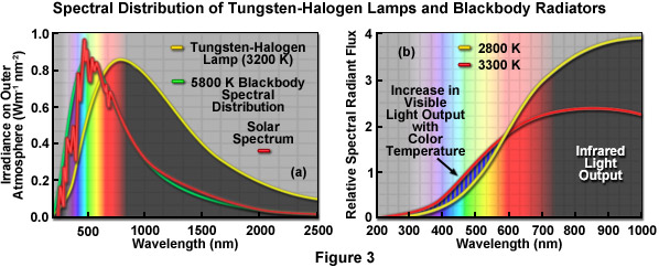
In summary, as incandescent radiators, tungsten-halogen lamps generate a continuous spectrum of light that ranges from the central ultraviolet through the visible and into the infrared wavelength regions (see Figures 1 and 3). Compared with the emission spectrum of sunlight and a theoretical 5800 K blackbody radiator (as presented in Figure 3(a)), the longer wavelength regions always predominate in tungsten-halogen lamps. However, as filament temperature increases in a tungsten-halogen lamp, the light emission profile shifts to shorter wavelengths so that as temperature approaches the limiting melting point of tungsten, the proportion of visible wavelengths emitted by the lamp increase substantially. This effect is illustrated in Figure 3(b) by normalizing the output distribution of lamp radiation at color temperatures of 2800 K and 3300 K to the same luminous flux. In addition to having a significantly smaller proportion of radiation in the infrared wavelengths, the 3300 K curve exhibits a much larger output in the visible wavelengths.
The photometric characteristics for evaluating the performance of light sources are somewhat unusual in that two systems of units exist in parallel to define the important variables associated with radiance and spectral output. The physical photometric system treats light purely as electromagnetic radiation in terms of brightness (radiance) connected with units of length and angle, and measured in watts. The physiological photometric system takes into account the manner in which a hypothetical human eye evaluates the light source. As every human eye responds somewhat differently to the visible light spectrum, a standard eye has been defined by international convention. The primary characteristic of this standard is the sensitivity to different colors of light based on a maximal response to 550-nanometer (green-yellow) light, measured in units of lumens rather than watts. The physiological system is adequate if the light detector is the human eye, a digital camera, photographic film, or some other type of device that responds similarly. However, this system will fail if the light under analysis falls into the ultraviolet or infrared regions that are invisible to the human eye. In this case, the physical photometric system must be employed for measurements and analysis.
Tungsten-Halogen Microscopy Lamp Specifications
|
|||||||||||||||||||||||||||||||||||||
Table 1
Presented in Table 1 are electrical specifications, filament dimensions, typical life span, and the photometric output for several of the most popular tungsten-halogen lamps currently utilized in optical microscopy. Among the most important terms used to compare these lamps are the luminous flux, which is the total light emitted as measured in lumens. Luminous flux increases in proportion to its physical photometric equivalent in watts. Another important quantity, known as luminous intensity, is that part of the luminous flux that is measured by a solid angle in a single direction. Luminous intensity, having units of candelas, is used to evaluate lamp performance in an optical system. Lamps are also rated in terms of luminous efficacy using lumens per watt of electrical power (relating the physical and physiological systems) to determine the efficiency with which electrical power is converted to visible radiation. The theoretical maximum in luminous efficacy is 683 lumens per watt, but in practice, tungsten-halogen lamps typically achieve a limit of 37 lumens per watt. In order to more clearly understand the electrical characteristics of tungsten-halogen lamps, the following generalizations can usually be applied: for every 5 percent change in the voltage applied to the lamp, the life span is either doubled or halved, depending upon whether voltage is decreased or increased. In addition, each 5 percent change in voltage is accompanied by a 15 percent change in luminous flux, an 8 percent change in power, a 3 percent change in current, and a 2 percent change in color temperature.
A wide variety of tungsten-halogen lamp designs incorporate integral reflectors that serve to efficiently gather light wavefronts emitted by the lamp and direct them into the illumination system in an organized manner. Termed reflector lamps (see Figure 4), these pre-assembled units have found widespread application as external illuminators for stereomicroscopy applications. Light from the illuminator can be directed to any region of the specimen with a flexible fiber optic light guide. Reflector lamps vary widely in design with regards to reflector features and geometry, as well as alignment of the lamp within the reflector. However, all reflector lamps incorporate single-ended lamps, which are mounted in the center of the reflector optical axis with the base cemented into the reflector apex. Filament configuration is generally determined by the beam characteristics required by the particular optical system for which the lamp is targeted. All filament designs, including transverse, axial, and flat-core, are used in reflector lamps.
Reflector lamps are generally connected to lamp holders with molybdenum pins projecting outwards from the rear of the reflector and mounted with ceramic covers. In some cases, specialized cable connections are utilized to spatially separate the electrical contact from the heat source (the lamp). Because reflector lamps usually are incorporated as part of a precisely aligned optical system, the electrical connection is only occasionally used as part of the mount. There are several methods for mounting reflectors, including the incorporation of a holder at the front edge of the reflector, using pressure on the back of the reflector closure, centering the reflector edge in a cone, and adjusting the reflector edge at an angular stop. In most cases, the reflector base design and mounting mechanism is used to designate the particular class of a reflector lamp. The external diameter of the reflector front opening is the defining criteria for reflector lamps, and two basic sizes have been established by the manufacturers. These are designated MR 11 and MR 16, with the letters being the abbreviation for metal reflector and the digits referring to the reflector diameter in eighths of an inch. Thus, the MR 16 reflector lamp has a diameter of approximately 50 millimeters whereas the MR 11 lamps have a diameter of almost 35 millimeters.
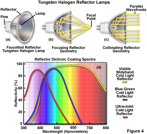
Tungsten-halogen reflectors are designed to either focus or collimate light emitted by the lamp, as illustrated in Figure 4. Focusing reflectors concentrate the light on a small spot (the focal point) in the central optical axis at a defined distance from the reflector (see Figure 4(b)). This type of reflector is designed with an elliptical geometry, which requires that the lamp filament be placed in the first focal point of the ellipsoid so that the projected light spot is concentrated at the second focal point. In designing lamphouses for focusing reflectors, the most important criterion is mounting the lamp at the proper distance from the optical system input aperture. Collimating reflectors have a parabolic geometry in order to generate a parallel beam of light having beam characteristics that are defined by the lamp parameters and reflector size (see Figure 4(c)). The emerging beam angle is primarily determined by the size of the lamp filament and the free aperture of the reflector. In most cases, a round-core axial filament ensures a rotationally symmetrical beam.
Reflectors are generally fabricated from glass, but some are also made with aluminum. Their inner walls can be either smooth or structured with facets to control light distribution. Internal structure ranges from fine, barely visible grains to large, tiled facets (see Figure 4(a)). In glass reflectors, the inner domed reflector surface is coated (usually by vapor deposition) to obtain the required reflective properties. The dimensional stability of glass reflectors is superior to that of metal reflectors and the ability to choose specific coating materials, including those that can change the spectral character of reflected light, renders these reflectors far more versatile. Metal reflectors are far easier and cheaper to fabricate, but they are limited in spectral output control and are more prone to fluctuations in geometric tolerances during operation.
If the entire spectrum of radiation emitted by the lamp is required, or in cases where infrared light is useful, metal reflectors or glass reflectors with a thin gold coat are the optimum choice. However, where specific reflection properties must be used to select wavelengths through interference, dichroic thin-film coatings on glass reflectors are optimal. These coatings consist of approximately 40-60 very thin layers, each only a quarter wavelength of light thick and composed of alternating materials having a high and low refractive index. Fine tuning of the thickness and number of layers enables designers to generate a wide variety of spectral output characteristics. Among the dichroic reflector lamps, the most useful for microscopy is termed a cold-light reflector because only visible light in the wavelength region of 400 to 700 nanometers is sent to the optical system (Figure 4(d)). Infrared wavelengths radiate through the rear of the reflector and are pumped away from the lamphouse with an electrical fan. The application of suitable cold-light reflectors reduces the overall thermal load on the illumination system and produces light that can be recorded with film and digital cameras.
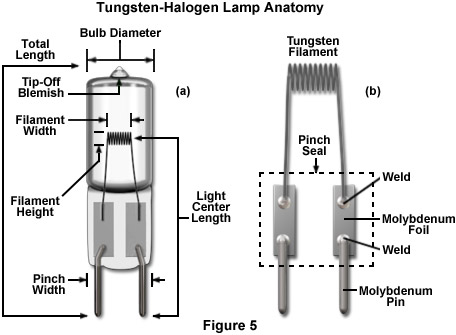
The basic anatomy of a single-ended tungsten-halogen lamp commonly used for illumination in optical microscopy is illustrated in Figure 5. The total length is measured from the end of the base pin to the point of the sealed exhaust tube. An important criterion for lamp positioning with respect to the collector lens system is the light center length (Figure 5(a)), which locates the center of the filament to a defined reference plane in the lamp base. Other important parameters are the bulb diameter (thickest portion of the envelope), the pinch width of the base (usually slightly greater than the bulb diameter), and the dimensions of the filament field (height and width). The effective size of the illumination source used in designing the output optical system is determined by the height and width of the filament (the filament field). The tolerances and filament field position are critical and should not deviate by more than 1 millimeter from the lamp's axis of symmetry (defined by the plane of the base pins and the lamp centerline). Filament field tolerances are designed for a particular filament architecture and should be measured when the filament is hot.
The excessively high operating temperatures of tungsten-halogen lamps require substantially stronger and thicker transparent envelopes than conventional tungsten and carbon lamps. Fused silica quartz glass is the standard material used in the fabrication of tungsten-halogen lamps because this material can withstand envelope temperatures up to 900° C and operating pressures approaching 50 atmospheres. In general, the optical quality of quartz lamp envelopes is considerably lower than that of the blown glass bulbs used to manufacture conventional incandescent lamps. This artifact is due to the fact that the quartz is more difficult to process (primarily because of the higher melting point). The quartz targeted for lamp envelopes starts as a cylindrical tube that is first cut to the proper length before a smaller exhaust tube is attached. Later in the manufacturing process, after the filament and lead pins are inserted and pinched, the envelope is filled with the appropriate gas and halogen compound before the exhaust tube is removed and sealed in a process referred to as tip-off, which leaves a visible blemish in the envelope. Tungsten-halogen lamps used in microscopy generally have the tip-off blemish located at the top of the envelope in a region that does not interfere with the optical quality of the light emitted by the lamp (Figure 5(a)). The prefabricated internal lamp structural elements (filament, foil connector, and pins) are inserted into the tubular quartz before the lead pins are hermetically sealed into the envelope by pinching. The outer surface of the pinch is shaped to ensure maximum mechanical strength.
After the pin leads are pinched (this process is conducted while the envelope is flushed with an inert gas to avoid oxidation) the bulb is filled through the exhaust tube with the appropriate gas containing 0.1 to 1.0 percent of a halogen compound. The inert fill gas can be either xenon, krypton, argon, or nitrogen, as well as a mixture of these gases having the highest average atomic weight consistent with the desired arc resistance. The halogen employed for the tungsten-halogen lamps used in microscopy is usually HBr, CH3Br, or CH2Br2. The high internal lamp pressure is achieved by filling the envelope to the desired pressure and immersing the lamp in liquid nitrogen to condense the fill gas. After sealing the exhaust tube at tip-off, the fill gas expands as it warms to ambient temperature. High performance tungsten-halogen lamps produced by Osram (Sylvania in the United States) feature Xenophot® technology where krypton gas is replaced with xenon, which has a higher atomic mass than krypton and the other fill gasses. Xenon provides better suppression of tungsten vaporization, enables higher filament temperatures, and increases the luminous efficacy by approximately 10 percent (corresponding to a color temperature increase of about 100 K). Xenophot lamps are marketed using the acronym HLX, which is derived from the terms Halogen, Low-voltage, and Xenon. Most of the tungsten-halogen lamps used in research microscopes are equipped with Osram/Sylvania HLX bulbs or their equivalent.
Tungsten is always used to fabricate wire filaments in modern incandescent lamps. In order to be suitable for tungsten-halogen lamps, the raw tungsten wire must undergo a complex doping and heat treatment process to bestow the ductility necessary for processing and to ensure that the filament does not distort over extended periods of high temperature during lamp operation. The wire must also be rigorously cleaned to prevent harmful gases from being emitted after the lamp has been sealed. The filament wire length is determined by the operating voltage, with higher voltages requiring longer lengths. The diameter is dictated by lamp power levels and the desired life span. High power levels require thicker filaments, which are also mechanically stronger. Filament geometry is largely responsible for the photometric properties of tungsten-halogen lamps. The lamps used in microscopy usually feature a flat-core filament geometry in which the wire is first wound into the shape of a rectangular rod, and then pinched across the long axis. Instead of being specified in terms of diameter and length, flat-core filaments are gauged by the length and width of the flat side of the filament and the thickness of the rectangular shape. Light emission characteristics of flat-core filament lamps deviate significantly from those of other geometries. The most substantial portion of emitted light is radiated perpendicular to the flat face of the filament, which is aligned with the collection optics for maximum throughput. Some lamp designs feature a specialized flat-core filament in which the light-emitting surface is square. These lamps are the preferred illumination sources in transmitted light microscopy.
One of the critical factors in the fabrication of tungsten-halogen lamps is sealing the internal elements to isolate them from the external atmosphere. Lead-in wires (molybdenum pins; Figure 5(b)) protrude from the lamp base, through the seal, to position and secure the lamp in a socket that is wired to a power source. The most important aspect of creating a seal is the difference in thermal expansion coefficients between quartz and the tungsten filament leads. Quartz has a very low expansion coefficient whereas that of tungsten is much higher. Without a proper seal, the lead-in wires would rapidly expand when the lamp became hot and shatter the surrounding glass. In modern tungsten-halogen lamps, a very thin molybdenum foil (2 to 4 millimeters wide and 10 to 20 micrometers thick; Figure 5(b)) is embedded in the quartz and each end of the foil is welded to short molybdenum connecting wires that are in turn welded to the filament and lead-in pin wires. Molybdenum is used in the seal because the razor-sharp edges enable it to be safely embedded into the quartz during the pinch operation. Lamps used for microscopy feature single-ended bases having either molybdenum pins projecting from the pinch or tungsten pins that are internally bonded to the molybdenum foil, as described above. The distance between the pins is standardized, with typical values being 4 and 6.35 millimeters (designated as G4 and G6.35; G for glass). Pin diameters range from 0.7 to 1 millimeter.
Because tungsten-halogen lamp fabrication technology is so well advanced at this point, the life of a typical lamp ends suddenly, usually upon powering up a cold lamp filament. During the course of an average life span, advanced tungsten-halogen lamps do not blacken and undergo only minor changes in photometric output characteristics. Similar to other incandescent lamps, tungsten-halogen lamp lifetimes are determined by the vaporization rate of tungsten from the filament. If the filament does not have a constant temperature along the entire length of the wire, but instead has regions of much higher temperature produced by uneven thickness or internal structural variations, then the filament will usually fail due to premature breakage in these regions. Even though vaporized tungsten is returned to the filament by the halogen regenerative cycle (discussed above), the material is unfortunately deposited on cooler regions of the filament and not those critical hot spots where thinning usually occurs. As a result, it is virtually impossible to predict when any particular filament will fail in lamps that are operated continuously. In those lamps that are switched on and off frequently, it is safe to assume that they will fail at some point when being switched on.
Tungsten-halogen lamps can be operated using power supplies with either direct or alternating current, but most research-level microscopy applications use direct current (DC) power supplies. The most advanced power supplies for tungsten-halogen lamps feature specialized circuitry that ensures current stabilization and suppressed ripple. The critical phase for a tungsten-halogen lamp is when voltage is first applied to a cold filament, a period when the filament resistance is approximately 20 times lower than it is at full operating temperature. Thus, when the supply voltage is instantaneously applied to the lamp by switching it on, a very high initial current flows (up to 10 times higher than steady-state; termed inrush current) that slowly drops as the filament temperature and electrical resistance increase. The peak current level is reached within a few milliseconds of startup, but is usually over in approximately half a second. Unfortunately, the high inrush current produced during a cold start has a negative effect on the life expectancy of the lamp. Specialized power supply circuitry (often referred to as a soft start circuit) is utilized to compensate for the high inrush currents in the most advanced applications (including microscopy) for which tungsten-halogen lamps are employed to conduct ratiometric measurements.
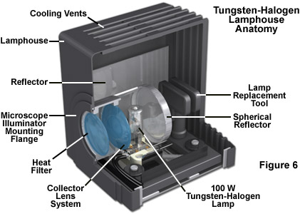
Illustrated in Figure 6 is a typical 100-watt tungsten-halogen lamphouse used in transmitted light microscopy applications. The lamphouse is equipped with cooling vents that allow convection currents to bathe the lamp with cooler air during operation. A metallic reflector lining the inside of the lamphouse assists the spherical reflector to direct the greatest possible level of luminous flux into the collector lens system for delivery to the microscope optical train. This advanced lamphouse contains a spare lamp holder and a plastic replacement tool that the operator can use to grip the lamp envelope during lamp switchover. Adjustments to the lamp position in relation to the spherical reflector and collector optical axis can be made using Allen screws that translate the base mount. The lamphouse is attached to the microscope illuminator using a proprietary mounting flange that couples the lamphouse to an upright or inverted microscope (although most lamphouses are not interchangeable from one brand of microscope to another). An infrared (heat) filter in front of the collector lens system absorbs a considerable amount of unwanted radiation, and additional filters can usually be inserted into the light path (using filter holder slots in the microscope illuminator) to absorb selected visible wavelength bands, adjust color temperature, or add neutral density (reducing light amplitude). Most microscopy lamphouses are not equipped with a diffusion filter, but these are often required to achieve even illumination across the viewfield and are usually placed in the microscope illuminator by the manufacturer.
Contributing Author
Michael W. Davidson - National High Magnetic Field Laboratory, 1800 East Paul Dirac Dr., The Florida State University, Tallahassee, Florida, 32310.