


Aperture correlation microscopy combines the light efficiency of structured illumination with the acquisition speed of a spinning disk confocal instrument. The technique holds the potential to push structured illumination microscopy (SIM) into new applications where high temporal resolution is mission-critical, while simultaneously maintaining the relatively simple instrumentation (especially the use of a white light source) of other SIM instruments. A necessary step for increasing the speed of SIM image acquisition involves abandoning offline demodulation techniques. Instead, demodulation must be conducted not only by illuminating the sample through a structured mask, but also by employing the same mask for detection in order to directly identify emission from the focal plane. The goal of aperture correlation microscopy is to overcome the limited light efficiency of traditional spinning disk systems where a multi-pinhole array is used to sweep across the specimen and probe the sample at several points in parallel. This interactive tutorial simulates a virtual aperture correlation microscope.

The tutorial initializes with the image of a thick tissue specimen appearing in the Widefield Image window and the corresponding optical section at the same focal depth presented in the Optical Section window. In order to operate the tutorial, use the Axial Focal Plane slider to transition through the widefield and optical section image stacks. The depth of the optical section is given in the small window at the right-hand side of the slider. A new specimen can be selected from within any set by using the Choose a Specimen pull-down menu. New specimen sets can be selected with the Set radio buttons.
The principle concept behind aperture correlation is to overcome the pinhole crosstalk limitation by using temporal rather than spatial coding. In effect, instead of probing each pixel only once with a spatially uniquely positioned pinhole, the idea is to probe each pixel multiple times but with a temporally unique sequence. Each pixel is presented with a sequence of pinhole illuminations that shows zero cross correlation to the sequence presented to any other pixel. Thus, for each pixel in the image, a temporal modulation of an aperture transmission according to an appropriate correlation sequence must be found (thus the name aperture correlation). The temporal coding necessary for aperture correlation can be achieved by a dense, random pattern of pinholes on a rotating disk. In this manner, each pixel will be probed several times through different pinholes, but for each pixel the illumination sequence will be random, and thus unique. A major limitation is that such an instrument cannot directly provide a confocal image as this would require negative transmission values for the blocking areas of the disk. In reality, the image detected through the disk contains all the in-focus information plus an offset representing out-of-focus information.
In order to calculate an optical section, the out-of-focus offset must be subtracted. Toward this end, the original design (see Figure 2(a)) included a blank sector on the disk through which a standard widefield image could be acquired. Scaled subtraction of both images resulted in an optical section. The primary advantage of this design is that the random pinhole pattern used for illumination and detection can be very closely packed. Therefore, up to 50 percent transmission efficiency can be achieved, which allows use of a standard white light source. In summary, the idea of aperture correlation allows for a very light-efficient disk design so that a normal white light source is sufficient and no laser illumination is required. However, in order to achieve this, the condition of directly acquiring an optical section must be relaxed, and the optical section has to be calculated by a scaled subtraction from two raw data images.
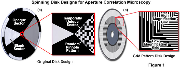
Presented in Figure 1 is the original disk design for aperture correlation microscopy (Figure 1(a)) along with the more advanced design using a grid line pattern (Figure 1(b)). In the original design, a random pinhole pattern is used that can only be optimized for one objective. In the more advanced grid pattern design, two different grid patterns are located on the same disk to eliminate the requirement for changing disks to match objective numerical aperture. In short, the magnification and numerical aperture of the objective combined with the spatial frequency of the grid pattern on the disk define optical section thickness. The high and low magnification patterns illustrated in Figure 1(b) are designed to be compatible with a wide range of objectives.
Contributing Authors
Matthias F. Langhorst - Carl Zeiss MicroImaging GmbH, Koenigsallee 9-21, 37081 Goettingen, Germany.
Tadja Dragoo and Michael W. Davidson - National High Magnetic Field Laboratory, 1800 East Paul Dirac Dr., The Florida State University, Tallahassee, Florida, 32310.