


Introduction
Traditional approaches to live-cell imaging are often based on short or long term time-lapse investigations designed to monitor cellular motility and dynamic events using common contrast enhancement techniques, including brightfield, differential interference contrast (DIC), Hoffman modulation contrast (HMC), phase contrast, and widefield fluorescence. However, modern techniques and newly introduced methodologies are extending these observations well beyond simply creating cinematic sequences of cell structure and function, thus enabling time-lapse imaging to be integrated with specialized modes for monitoring, measuring, and perturbing dynamic activities of tissues, cells, and subcellular structures.
A majority of the live-cell imaging investigations are conducted with adherent mammalian cells, which are positioned within 10 micrometers of the coverslip-medium interface. Increasingly, however, investigators are turning their attention to thicker animal and plant tissue specimens that can range in thickness from 10 to 200 micrometers. In virtually all live-cell imaging scenarios using widefield microscopy, out of focus information blurs the image and the constant churning of the cytoplasm creates limitations on exposure times. Both brightfield and fluorescence methods used for imaging thin as well as thicker animal tissues and plants must take into account the sensitivity of these specimens to light exposure and the problems associated with resolving features that reside more than 20 to 30 micrometers within the specimen.
Brightfield techniques are often less harmful to living cells, but methodology for observing specific proteins using transmitted illumination have not been widely developed. Generating a high-contrast chromatic (color) or intensity difference in a brightfield image is more difficult than identifying a luminous intensity change (in effect, due to fluorescence) against a dark or black background. Therefore, brightfield techniques find applications in following organelles or cell-wide behavior, while fluorescence methods, including confocal techniques, are generally used for following specific molecules.
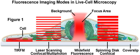
Presented in Figure 1 is a schematic illustration of popular imaging modes in widefield and scanning modes of fluorescence microscopy. Widefield, laser scanning, spinning disk, and multiphoton techniques employ vastly different illumination and detection strategies to form an image. The diagram illustrates an adherent mammalian cell on a coverslip being illuminated with total internal reflection (TIRFM), laser scanning, multiphoton, and spinning disk confocal, in addition to traditional widefield fluorescence. The detection patterns for each technique are indicated in red overlays. In widefield, the specimen is illuminated throughout the field as well as above and below the focal plane. Each point source is spread into a shape resembling a double-inverted cone known as the point-spread function (PSF). Only the central portion of this shape resides in the focal plane with the remainder contributing to out-of-focus blur, which degrades the image.
In contrast the laser scanning, multiphoton, and spinning disk confocal microscopes scan the specimen with a tightly focused laser or arc-discharge lamp (spinning disk). The pattern of excitation is a point-spread function, but a conjugate pinhole in the optical path of the confocal microscopes prevents fluorescence originating away from the focal plane from impacting the photomultiplier or digital camera detector. The laser scanning confocal microscope has a single pinhole and a single focused laser spot that is scanned across the specimen. In the spinning disk microscope, an array of pinhole or slit apertures, in some cases fitted with microlens elements, are placed on a spinning disk such that the apertures rapidly sweep over the specimen and create an image recorded with an area array detector (digital camera). In the multiphoton microscope, the region at which photon flux is high enough to excite fluorophores with more than one photon resides at the in-focus position of the point-spread function. Thus, fluorophore excitation only occurs in focus. Because all fluorescence emanates from in-focus fluorophores, no pinhole is required and the emitted fluorescence generates a sharp, in-focus image.
back to top ^Brightfield Microscopy and Transmitted Light Techniques
One of the primary and favorite techniques used in all forms of optical microscopy for the past three centuries, brightfield illumination relies upon changes in light absorption, refractive index, or color for generating contrast. As light passes through the specimen, regions that alter the direction, speed, and/or spectrum of the wavefronts generate optical disparities (contrast) when the rays are gathered and focused by the objective. Resolution in a brightfield system depends on both the objective and condenser numerical apertures, and an immersion medium is often required on both sides of the specimen (for numerical aperture combinations exceeding a value of 1.0). Digital cameras provide the wide dynamic range and spatial resolution required to capture the information present in a brightfield image. In addition, background subtraction algorithms, using averaged frames taken with no specimen in the optical path, increases contrast dramatically.
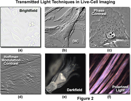
Simple brightfield imaging, with the microscope properly adjusted for K�hler illumination (see Figure 2(a)), provides a limited degree of information about the cell outline, nuclear position, and the location of larger vesicles. However, the general lack of contrast in brightfield mode renders this technique relatively useless for serious investigations of cell structure and function. Methods that enhance contrast include differential interference contrast (DIC), polarized light, phase contrast, Hoffman modulation contrast, and darkfield microscopy (examples are illustrated in Figure 2). Several of these techniques are limited by light originating in regions removed from the focal plane when imaging thicker plant and animal tissues, while polarized light requires birefringence (usually not present to a significant degree in animal cells) to generate contrast. The adherent Chinese hamster ovary cells presented in Figure 2(a) were imaged in brightfield illumination without the assistance of optical contrast-enhancing methodology. Note the general lack of contrast when compared to other images in the figure. Individual cells are difficult to distinguish and most of the internal features (for example, the nuclei) are not visible in this image.
Differential interference contrast microscopy (Figure 2(b) and Figure 3(a)) requires plane-polarized light and additional light-shearing (Nomarski or Wollaston) prisms to exaggerate minute differences in specimen thickness gradients and refractive index. Lipid bilayers, for example, produce excellent contrast in DIC because of the difference in refractive index between aqueous and lipid phases of the cell. In addition, cell boundaries in relatively flat adherent mammalian and plant cells, including the plasma membrane, nucleus, vacuoles, mitochondria, and stress fibers, which usually generate significant gradients, are readily imaged with DIC. In plant tissues, the birefringent cell wall reduces contrast in DIC to a limited degree, but a properly aligned system should permit visualization of nuclear and vacuolar membranes, mitochondria, chloroplasts, and condensed chromosomes in epidermal cells. Differential interference contrast is an important technique for imaging thick plant and animal tissues because, in addition to the increased contrast, DIC exhibits decreased depth of focus at wide apertures, creating a thin optical section of the thick specimen. This effect is also advantageous for imaging adherent cells to minimize blur arising from floating debris in the culture medium.
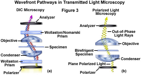
Polarized light microscopy (Figure 2(f) and Figure 3(b)) is conducted by viewing the specimen between crossed polarizing elements. Assemblies within the cell having birefringent properties, such as the plant cell wall, starch granules, and the mitotic spindle, as well as muscle tissue, rotate the plane of light polarization, appearing bright on a dark background. The rabbit muscle tissue illustrated in Figure 2(f) is an example of polarized light microscopy applied to living tissue observation. Note that this technique is limited by the rare occurrence of birefringence in living cells and tissues, and has yet to be fully explored. As mentioned above, differential interference contrast operates by placing a matched pair of opposing Nomarski prisms between crossed polarizers, so that any microscope equipped for DIC observation can also be employed to examine specimens in plane-polarized light simply by removing the prisms from the optical pathway.
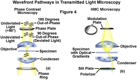
The widely popular phase contrast technique (as illustrated in Figure 2(c) and Figure 4(a)) employs an optical mechanism to translate minute variations in phase into corresponding changes in amplitude, which can be visualized as differences in image contrast. The microscope must be equipped with a specialized condenser containing a series of annuli matched to a set of objectives containing phase rings in the rear focal plane (phase contrast objectives can also be used with fluorescence, but with a slight reduction in transmission). Phase contrast is an excellent method to increase contrast when viewing or imaging living cells in culture, but typically results in excessive halos surrounding the outlines of edge features. These halos are optical artifacts that often reduce the visibility of boundary details. The technique is not useful for thick specimens (such as plant and animal tissue sections) because shifts in phase occur in regions removed from the focal plane that distort image detail. Furthermore, floating debris and other out-of-focus phase objects interfere with imaging adherent cells on coverslips.
Often metaphorically referred to as "poor man's DIC", Hoffman modulation contrast is an oblique illumination technique that enhances contrast in living cells and tissues by detection of optical phase gradients (see Figure 2(d) and Figure 4(b)). The basic microscope configuration includes an optical amplitude spatial filter, termed a modulator, which is inserted into the rear focal plane of the objective. Light intensity passing through the modulator varies above and below an average value, which by definition, is then said to be modulated. Coupled to the objective modulator is an off-axis slit aperture that is placed in the condenser front focal plane to direct oblique illumination towards the specimen. Unlike the phase plate in phase contrast microscopy, the Hoffman modulator is designed not to alter the phase of light passing through; rather it influences the principal zeroth order maxima to produce contrast. Hoffman modulation contrast is not hampered by the use of birefringent materials (such as plastic Petri dishes) in the optical pathway, so the technique is more useful for examining specimens in containers constructed with polymeric materials. On the downside, HMC produces a number of optical artifacts that render the technique somewhat less useful than phase contrast or DIC for live-cell imaging on glass coverslips.
The methodology surrounding darkfield microscopy, although widely applied for imaging transparent specimens throughout the nineteenth and twentieth centuries, is limited in use to physically isolated cells and organisms (as presented in Figure 2(e)). In this technique, the condenser directs a cone of light onto the specimen at high azimuths so that first-order wavefronts do not directly enter the objective front lens element. Light passing through the specimen is diffracted, reflected, and/or refracted by optical discontinuities (such as the cell membrane, nucleus, and internal organelles) enabling these faint rays to enter the objective. The specimen can then be visualized as a bright object on an otherwise black background. Unfortunately, light scattered by objects removed from the focal plane also contribute to the image, thus reducing contrast and obscuring specimen detail. This artifact is compounded by the fact that dust and debris in the imaging chamber also contribute significantly to the resulting image. Furthermore, thin adherent cells often suffer from very faint signal, whereas thick plant and animal tissues redirect too much light into the objective path, reducing the effectiveness of the technique.
back to top ^Widefield Fluorescence Microscopy
In live-cell imaging applications, widefield fluorescence microscopy is useful for observing the dynamics of adherent cells grown in specialized environmental chambers that adapt to a microscope stage. In the most rudimentary configuration, a standard inverted tissue culture microscope equipped with epi-fluorescence illumination is coupled to an area array detector system (usually a CCD camera), the appropriate fluorescence filters, and a shutter system to limit excessive exposure of the cells to harmful excitation light. Basic fluorescence microscopy relies upon carefully matched interference filters in selecting specific bandwidths for illumination and detection of emission. Light sources include mercury, xenon, and metal halide arc-lamps, beam-expanded laser systems, and light-emitting diodes (LEDs), all of which require different filter specifications. Synthetic fluorophores useful in fluorescence microscopy feature emission spectra that cover the near-ultraviolet, visible, and near-infrared regions. The application of genetically-encoded fluorescent proteins has dramatically expanded the capabilities of live-cell imaging in fluorescence microscopy by enabling investigators to target subcellular regions of interest with exacting precision.
In widefield fluorescence, the full aperture of emission light gathered by the microscope objective maximizes the recorded signal and simultaneously minimizes the required exposure times. Thus, specimens can be imaged with very brief illumination periods. The major drawback to widefield imaging is that fluorescence arising from regions far removed from the focal plane, as well as background signal, contributes non-useful light that often obscures the features of interest. Therefore, widefield imaging achieves the optimum results when the features of interest are either large (such as an organelle) or highly punctate in nature. A wide variety of live-cell specimens, including adherent cells, bacteria, yeast, and very thin tissue sections, are ideal candidates for imaging in widefield fluorescence, however, thicker tissues (exceeding 5 micrometers) are best imaged using the more advanced methodology discussed below.
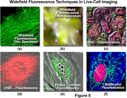
Even though there have been numerous advances in the development of synthetic fluorescent dyes, quantum dots, and fluorescent proteins for imaging in fluorescence mode, in some cases it is advantageous to combine fluorescence with other imaging modalities. As an example, DIC microscopy can be used in conjunction with widefield fluorescence (Figure 5(c)) to monitor cell viability and general morphology while simultaneously investigating phenomena of interest with specifically labeled targets. Capturing DIC and fluorescence in a single image frame is usually not practical, but in properly configured microscopes, the two techniques can be used sequentially. Thus, the DIC image can be captured from a fluorescently labeled specimen using transmitted light followed by imaging in epi-fluorescence mode. The two images can be combined during analysis. Advanced widefield microscope configurations can capture DIC and fluorescence images simultaneously using spectrally separated (such as visible and near-infrared) illumination and a dual camera or split-view camera adapter. In most laser scanning confocal microscopes (discussed below), images can be acquired simultaneously in fluorescence and DIC mode, thus eliminating the need for post-acquisition processing. Phase contrast and Hoffman modulation contrast (Figures 5(d) and 5(e)) can also be successfully employed in combination with widefield fluorescence microscopy. However, in these techniques the objectives are directly modified, either with a phase ring or a Hoffman modulation plate, which will result in a loss of emission intensity amounting to 5-15 percent.
As a note of caution, when combining DIC, phase contrast or Hoffman modulation contrast with fluorescence, especially in live-cell imaging, the loss of emission light passed through a DIC analyzer, the objective phase ring, or the Hoffman modulation plate in the rear focal plane of the objective can be severe. In the former case, the DIC analyzer and Nomarski prisms should be removed from the beam path before capturing fluorescence images, but the phase and Hoffman objectives contain modified optical elements that cannot be removed. Light loss through a phase ring or Hoffman modulator is not as significant as that lost through a polarizer and may not affect many applications. However, in specimens stained with weakly fluorescent probes or having low abundance targets, the gain in sensitivity obtained by using high transmission objectives can be crucial.
Illustrated in Figure 5 are a series of images captured using widefield fluorescence microscopy, either alone or in combination with several of the transmitted light techniques described above. Live human carcinoma cells (HeLa line) expressing a fusion of enhanced green fluorescent protein (EGFP) fused to human cytokeratin are shown in Figure 5(a). The adherent HeLa cells are approximately 3 to 5 micrometers in thickness and remain in focus throughout the image. In contrast, thick tissue specimens (mouse stomach; Figure 5(b)) are difficult to resolve in widefield fluorescence due to contributions from fluorescent structures not residing in the microscope focal plane. Widefield fluorescence can be used in combination with a variety of transmitted light techniques, including DIC (mouse kidney thin section; Figure 5(c)), Hoffman modulation contrast (embryonic mouse cells; Figure 5(d)), and phase contrast (rabbit kidney cells; Figure 5(e)). Using a combination of interference filter sets (Indian Muntjac cells; Figure 5(f)), multiple fluorophores can be sequentially imaged to elucidate the spatial and temporal relationships between labeled targets in living cells.
back to top ^Laser Scanning Confocal Microscopy
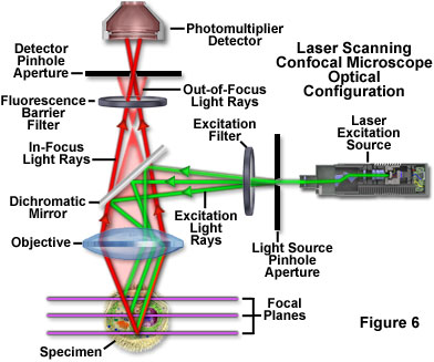
Laser scanning confocal microscopy offers several advantages over conventional widefield fluorescence microscopy, including controllable depth of field, the elimination of image degrading out-of-focus information, and the ability to collect serial optical sections from thick specimens. The key to the confocal approach is the use of spatial filtering to eliminate out-of-focus light or flare in specimens that are thicker than the plane of focus by illuminating the objective through a pinhole (see Figure 6 and Figure 8(b)). An image of the pinhole in the form of a small spot is formed on the specimen by a focused laser driven by a galvanometer-based scanning system. This spot, in turn, forms a reflected epi-fluorescence image on the original pinhole. If the specimen is in focus, the light passes through the pinhole to a detector (usually a photomultiplier). When the specimen is not in focus, the light reflected from it is defocused at the pinhole and very little passes through. Thus, fluorescence emission returning from the specimen to the detector is spatially filtered. As the pinhole aperture is reduced in size, it blocks more of the stray light from being detected but also lowers the total signal level. Although the absolute signal value is far less than observed with the widefield microscope configuration, rejecting the light from other focal planes increases the specific signal-to-noise ratio for the features of interest.
Additional advantages of laser scanning confocal microscopy include the ability to adjust magnification electronically by varying the area scanned by the laser without having to change objectives. This feature is termed the zoom factor, and is usually employed to adjust the image spatial resolution by altering the scanning laser sampling period. Increasing the zoom factor reduces the specimen area scanned and simultaneously reduces the scanning rate. The result is an increased number of samples along a comparable length, which increases both the image spatial resolution and display magnification on the host computer monitor. Confocal zoom is typically employed to match digital image resolution with the optical resolution of the microscope when low numerical aperture and magnification objectives are being used to collect data. The zoom control should be used with caution due to the fact that high zoom factors lead to increased photobleaching. In general, successful confocal imaging is a tradeoff between obtaining suitable zoom factors and imaging the specimen (especially when acquiring optical sections) without incurring significant photobleaching levels.
The major disadvantage of conventional laser scanning confocal microscopy for imaging cells and tissues is that the image is gathered by raster-scanning the specimen, which is relatively slow and often requires several seconds or longer per image. There is also a high degree of risk from irradiating the specimen with intense laser light that can produce phototoxicity in living cells. In most cases, the dwell time of the laser beam at any position on the specimen is only a few microseconds. Therefore, the laser excitation energy must be high enough to generate useable signal during that dwell time, often leading to complete saturation of all the fluorophores residing in the spot. Under these conditions, rapid photobleaching occurs, and gathering images with a high intrascene dynamic range (a significant number of gray levels) is challenging. For live-cell imaging over prolonged periods, the laser intensity should be reduced as much as possible. The major challenge for live-cell imaging using laser scanning confocal microscopes is to generate sufficient contrast while reducing phototoxicity, especially in cases where the cells are imaged for prolonged periods.
back to top ^Spinning Disk Confocal Microscopy
A variation of the galvanometer-based confocal microscope is the spinning disk confocal microscope, which can operate in real time (30 frames per second) or even faster to capture dynamic events in a wide spectrum of timescales. The principle is based on a Nipkow-style disk that is opaque with the exception of thousands of drilled or etched pinholes, often covered with miniature focusing lenses, arranged in interleaved Archimedean spiral patterns. Each illuminated pinhole on the disk is imaged by the objective to a diffraction-limited spot on the specimen. The fluorescence emission reflected from the specimen can be observed and recorded after it has passed back through the Nipkow disk pinholes. Several thousand points on the specimen are simultaneously illuminated by the disk achieving, in effect, several thousand confocal microscopes, all running in parallel. Spinning the disk fills in the spaces between the holes and creates a real-time confocal image that can be directly observed with the naked eye, as with the standard microscope.
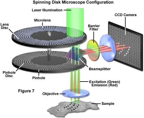
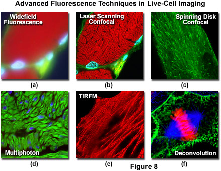
An alternative to the Nipkow disk involves recent technology that offers high light throughput using a disk that is etched with a pattern of perpendicular slits, rather than pinholes, providing greater transmission while maintaining an acceptable level of confocality (Figure 7). Unlike the Nipkow-style disks, these slit-pattern disks are produced with varying slit widths that match different objective numerical apertures, magnifications, and specimen thicknesses. Thus, the slit disks enable confocal images to be acquired at high resolution using objectives ranging in magnification from 10x to 100x. Both spinning disk designs were developed primarily for live-cell imaging applications where a compromise exists between the needed increase in image acquisition speed versus a slight loss in axial resolution (Figure 8(c)). Most spinning disk microscopes are illuminated with lasers or arc lamp sources and are coupled to sensitive electron-multiplying CCD cameras in order to image faintly fluorescent specimens.
Several manufacturers have introduced confocal systems using laser light shaped into a line, rather than a point, to scan the specimen, but with a substantial decrease in image acquisition time at the expense of resolution (usually a factor of 1.2 in one dimension). Unlike the case with spinning disk microscopy, the degree of confocality can be controlled by the user by invoking changes to the line shape and size. Line scanning microscopes are used with CCD camera systems rather than photomultipliers and are generally much faster in acquisition speed than spinning disk or laser scanning confocal microscopes. In summary, there has been a tremendous explosion in the popularity of confocal microscopy in recent years, due in part to the relative ease with which extremely high-quality images can be obtained from specimens prepared for conventional optical microscopy, and its great number of applications in many areas of current research interest.
back to top ^Multiphoton Microscopy
Excitation in multiphoton microscopy is a non-linear process that occurs only at the focal point of a diffraction-limited microscope, providing the ability to optically section thick biological specimens in order to obtain three-dimensional resolution. Individual optical sections are acquired by raster scanning the specimen in the x-y plane, and a full three-dimensional image is composed by serially scanning the specimen at sequential axial (z) positions, similar to the case in confocal microscopy (to produce optical sections). Because the position of the focal point can be accurately determined and controlled, multiphoton fluorescence is especially useful for probing selected regions beneath the specimen surface. The highly localized excitation energy serves to minimize photobleaching of fluorophores to those residing in the focal plane and thus reduces phototoxicity, which increases sample viability and the subsequent duration of experiments that investigate the properties of living cells and tissues. In addition, the application of near-infrared excitation wavelengths permits deeper penetration into biological materials and reduces the high degree of light scattering that is observed at shorter wavelengths. These advantages enable researchers to conduct experiments on thick living tissue samples (see Figure 8(d)), such as brain slices and developing embryos that would be difficult, if not impossible, to image with other microscopy techniques.
back to top ^Advanced Fluorescence Microscopy Applications
Total internal reflection fluorescence microscopy (TIRFM) is a technique designed to probe the surface of fluorescently labeled living cells with an evanescent wave generated by a light beam traveling between two media of differing refractive indices. In practice, an incident laser beam is reflected at a critical angle (total internal reflection) when it encounters the interface between a microscope glass coverslip and the aqueous medium containing the cells. Fluorophores within a few 10s of nanometers of the surface (between 10 and 200 nanometers) are excited by the evanescent wave, while those farther away are largely unaffected, as the energy of the evanescent wave declines exponentially with distance from the coverslip. Therefore, TIRFM results in a high signal level arising from fluorophores residing close to the coverslip, superimposed on a very dark background, providing the best possible signal-to-noise ratio. The extreme limitation on excitation depth is ideal for studying single molecules or membrane and organelle components near the surface of the coverslip in adherent cells (see Figure 8(e)). As excitation is limited to the thin region adjacent to the coverslip, photobleaching and phototoxicity are also limited to these areas, rendering TIRFM one of the most useful methodologies for long-term observations. The technique has become a fundamental tool to investigate a wide spectrum of phenomena in cell and molecular biology.
Deconvolution analysis is a technique that applies algorithms to a through-focus stack of images acquired along the optical (z) axis to enhance photon signals specific for a given image plane or multiple focal planes in an image stack. The microscope must be equipped with a high-precision motorized focus drive in order to guarantee image acquisition at precisely defined intervals between focal planes in the specimen. In a typical application (see Figure 8(f)), deconvolution analysis is utilized to deblur and remove out-of-focus light from a particular focal plane of interest using widefield fluorescence excitation and emission (although the technique is useful for other illumination modes as well). The most sophisticated applications apply deconvolution analysis to an entire image stack to produce projection views or three-dimensional models. The stack of widefield images used for deconvolution analysis captures the theoretical maximum number of photons emitted by the specimen. The process of deconvolution reassigns the "blur" intensity arising from photons emitted above and beneath the focal plane to the plane of origin. Therefore, deconvolution uses practically all of the available emission intensity and offers the best possible light budget, thus making this technique the method of choice for extremely photosensitive specimens.
An adaptation of the resonance energy transfer phenomenon to fluorescence microscopy, fluorescence or Förster resonance energy transfer (FRET) is used to obtain quantitative temporal and spatial information about the binding and interaction of proteins, lipids, enzymes, and nucleic acids in living cells. FRET microscopy is performed using either steady state or time-resolved techniques, but time-resolved FRET imaging has the advantage of more accurately mapping the donor-acceptor distance. A standard widefield fluorescence microscope equipped with the proper excitation and emission filters and a sensitive video camera can be utilized to perform FRET imaging. Biosensors that sandwich an environmentally sensitive protein or peptide between two FRET-capable fluorescent proteins are currently enjoying widespread use in cell biology. These probes are readily imaged in widefield fluorescence microscopy using sensitized emission FRET techniques coupled to ratiometric analysis. In addition, spectral imaging and linear unmixing with laser scanning confocal microscopes is useful for monitoring FRET in biosensors and other fluorescent protein applications.
Fluorescence lifetime imaging microscopy (FLIM) is a sophisticated technique that enables simultaneous recording of both the fluorescence lifetime and the spatial location of fluorophores throughout every location in the image. The methodology provides a mechanism to investigate environmental parameters such as pH, ion concentration, solvent polarity, non-covalent interactions, viscosity, and oxygen tension in single living cells, presenting the data in a spatial and temporal array. FLIM measurements of the nanosecond excited state lifetime are independent of localized fluorophore concentration, photobleaching artifacts, and path length (specimen thickness), but are sensitive to excited state reactions such as resonance energy transfer. In fact, combining FLIM with FRET by monitoring the change in lifetime of the fluorescent donor before and after being involved in resonance energy transfer is considered to be one of the best approaches for examining this phenomena.
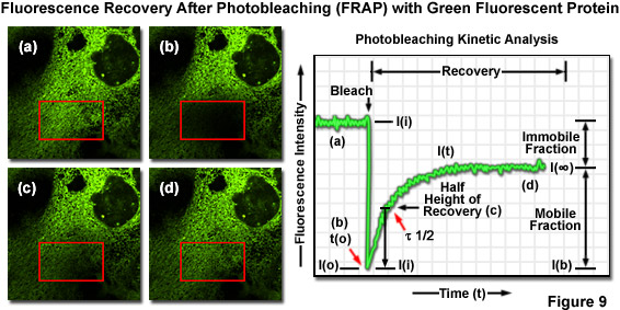
Translational mobility (lateral diffusion coefficients) of fluorescently labeled macromolecules and small fluorophores can be determined by fluorescence recovery after photobleaching (FRAP) techniques. In FRAP, a very small, selected region (several micrometers in diameter) is subjected to intense illumination, usually with a laser, to produce complete photobleaching of fluorophores in the region. The result is a dramatic reduction or annihilation of fluorescence. After the photobleaching pulse, the rate and extent of fluorescence intensity recovery in the bleached region is monitored as a function of time at lower excitation intensity to generate information about repopulation by fluorophores and the kinetics of recovery (Figure 9). FRAP is generally conducted using EGFP or other fluorescent proteins. Related photoactivation techniques are based on specialized synthetic caged fluorophores or similarly endowed fluorescent proteins that can be activated by a brief pulse of ultraviolet or violet light. Photoactivation and FRAP can be used as complementary techniques to determine mobility parameters.
In a technique related to FRAP (termed fluorescence loss in photobleaching; FLIP), a defined region of fluorescence within a living cell is subjected to repeated photobleaching by illumination with intense irradiation. Over a measured time period, this action will result in complete loss of fluorescence signal throughout the cell if all of the fluorophores are able to diffuse into the region that is being photobleached. By calculating the rate at which fluorescence is extinguished from the entire cell, the diffusional mobility of the target fluorophore can be determined. Furthermore, FLIP will readily identify the location and nature of any diffusional barriers between the individual compartments of a cell, such as the barrier between the soma and axon of a neuron.
The increasing use of multiple fluorescent proteins with highly overlapping emission spectra in live-cell imaging often requires unique solutions to provide adequate separation of signals from different targets. Spectral imaging relies on specialized hardware (primarily coupled to confocal microscopes) to separate the emission light into its spectral components. Linear unmixing is a computational process related to deconvolution that uses the unique spectral profile of each fluorophore in the specimen to reassign signal to the appropriate pixels in the final image. Although together these analytical tools can be employed to discriminate between distinct fluorophores having highly overlapping spectra, they operate at the cost of requiring that significantly more photons be detected from each pixel, which can be problematic for live-cell imaging of specimens labeled with dim fluorophores or low abundance targets.
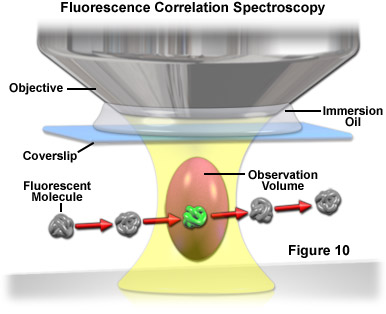
Used primarily with laser scanning confocal or multiphoton microscopy, fluorescence correlation spectroscopy (FCS) is a technique designed to determine molecular dynamics in volumes containing only one or a few molecules, yielding information about chemical reaction rates, diffusion coefficients, molecular weights, flow rates, and aggregation. In FCS, a small volume (approximately one femtoliter; the diffraction limited focal spot of a laser beam) is irradiated with a focused laser beam to record spontaneous fluorescence intensity fluctuations arising from the dynamics of fluorescent molecules occupying the volume as a function of time (see Figure 10). Relatively small fluorophores diffuse rapidly through the illuminated volume to generate short, randomized bursts of intensity. In contrast, larger complexes (fluorophores bound to macromolecules) move more slowly and produce a longer, more sustained time-dependent fluorescence intensity pattern.
The inherent dynamics and spatial distribution of fluorescently labeled structures can be difficult to analyze when these entities are densely packed and overlapping within specific regions of living cells. Fluorescent speckle microscopy (FSM) is a technique compatible with almost all imaging modalities that takes advantage of a very low concentration of fluorescently labeled subunits to reduce out-of-focus fluorescence and improve visibility of labeled structures and their dynamics in thick regions. FSM is accomplished by labeling only a fraction of the entire structure of interest. In that sense, it is similar to performing FCS over an entire field of view, albeit with more emphasis on spatial patterns than on quantitative temporal analysis. Speckle microscopy (as it is often called) has been especially useful in defining the mobility and polymerization of cytoskeletal elements, such as actin and microtubules, in highly motile cells.
The major benefit of coherent anti-stokes Raman scattering microscopy (CARS) is that it enables investigations of biomolecules without the addition of synthetic fluorescent labels or endogenous coupling to fluorescent proteins. Instead, the technique is based on the vibrational properties of the target molecule and does not require the species to be electronically excited by ultraviolet or visible light. In practice, fast (picosecond or lower) laser pulses in the near-infrared region from two sources are focused onto the specimen with a microscope objective and raster scanned in the lateral and axial planes. The pulses are separated in frequency by a selected molecular vibrational mode and generate a new beam, which has a wavelength shorter than the incident beams, at the objective focal point. The secondary beam produces a concentration profile of the target species and enables the construction of a three-dimensional image of the specimen. Because most of the biomolecules found in living cells have similar building blocks, it is difficult to achieve real molecular specificity in CARS experiments. Furthermore, CARS is based on resonance, meaning its sensitivity is restricted by the fact that thousands of molecules must be present in the focal volume for a significant signal level to be produced. Therefore, CARS (in its present form) must target abundant molecules and may be restricted to relying on external labeling (such as the use of deuterated compounds) to provide real molecular specificity.
Harmonic generation microscopy is an emerging technique that may ultimately see widespread use in live-cell imaging. Harmonic generation occurs when an optical excitation event involving two or more photons at a particular frequency results in cooperative emission at multiple harmonics (primarily, the second and third) without absorption of the photons. Generation of the harmonic frequencies is essentially a non-linear scattering process yielding an emitted photon wavelength that is twice the frequency or half the wavelength (for second harmonic generation) of the incident illumination. In optical microscopy, transparent specimens that lack symmetry (such as living cells) are ideal candidates for imaging with harmonic generation techniques. Unlike the situation with typical probes and traditional fluorescence microscopy illumination techniques, changing the excitation illumination wavelength produces a corresponding change in the emission wavelength. In addition, the emitted light is coherent and retains phase information about the specimen.
For ultra-high optical resolution, near-field scanning optical microscopy (NSOM) is currently the photonic technique of choice. Near-field imaging occurs when a sub-micron optical probe is positioned a very short distance from the sample and light is transmitted through a small aperture at the tip of this probe. The near-field is defined as the region above a surface with dimensions less than a single wavelength of the light incident on the surface. Within the near-field region evanescent light is not diffraction limited and nanometer spatial resolution is possible. This phenomenon enables non-diffraction limited imaging and spectroscopy of a sample that is simply not possible with conventional optical imaging methodology. Although currently seldom applied to live-cell imaging, related techniques such as atomic force microscopy are being explored to examine the surface of living cells.
Exhibiting spatial resolution well beyond the diffraction limit, stimulated emission depletion microscopy (STED) is an emerging superresolution technique that uses a donut-shaped depletion beam surrounding a smaller excitation beam to achieve an axial resolution lower than 50 nanometers. The technique relies on inhibiting fluorescence of excited molecules at the periphery of a laser scanning focal spot using synchronized laser pulses for excitation of fluorophores and spatially coordinated circular STED pulses to deplete emission. Resulting fluorescence is inhibited at the periphery of the spot, but not in the center, thus dramatically reducing the fluorescence spot size with a concomitant increase in resolution. STED has been demonstrated to be a useful tool for examining living cells at high resolution. Other emerging superresolution techniques, such as photoactivated localization microscopy (PALM) and structured illumination microscopy (SIM) will probably become essential tools in live-cell imaging in the near future.
Conclusions
The increasing use of genetically-encoded fluorescent proteins and advanced synthetic fluorophores for live-cell imaging has opened the door to a wide spectrum of new optical modalities that are useful for monitoring temporal dynamics and spatial relationships. The microscopist now has a full complement of tools to view and record image data of cellular processes that occur over a large range of timescales and at multiple resolutions. Slower events are readily observed and recorded using laser scanning confocal microscopy, while the more rapid dynamics are accessible through the use of spinning disk techniques. Additionally, multiphoton microscopy enables imaging deep within thick tissues and total internal reflection techniques are able to probe the membrane surface with confocal precision. Advanced fluorescence methodology, such as FRET, FLIM, FRAP, FCS, FSM, SIM, PALM, and STED, can be used to monitor protein-protein interactions, often at resolutions greater than those allowed by the diffraction barrier. As fluorophore, microscope, and detector technology becomes increasingly more advanced, a still wider range of phenomena will be put "under the microscope".
Contributing Authors
Michael E. Dailey - Department of Biological Sciences and Neuroscience Program, 369 Biology Building, University of Iowa, Iowa City, Iowa, 52242.
Sidney L. Shaw - Department of Biology, Indiana University, Bloomington, Indiana, 47405.
Jason R. Swedlow and Paul D. Andrews - Division of Gene Regulation and Expression, MSI/WTB Complex, University of Dundee, Dundee DD1 5EH, Scotland.
Matthias F. Langhorst - Carl Zeiss MicroImaging GmbH, Koenigsallee 9-21, 37081 Goettingen, Germany.
Michael W. Davidson - National High Magnetic Field Laboratory, 1800 East Paul Dirac Dr., The Florida State University, Tallahassee, Florida, 32310.